Testing Your Antenna with a NanoVNA: What the Numbers Mean and What to Do About Them
The NanoVNA has one job on your bench: it tells you whether your antenna is actually working at the frequency you care about. That's it. Everything else is in service of that one question.
This post walks through connecting your antenna, running the measurement, and reading what comes back. No RF engineering degree required.
What the NanoVNA is actually measuring

When your radio transmits, it sends power down the coax toward the antenna. If the antenna is a good match at that frequency, most of the power goes out as a radio wave. If it's a bad match, some bounces back. That bounce is wasted power, and it can stress your radio's output stage over time.
The NanoVNA measures that bounce. Three numbers matter:
- SWR (Standing Wave Ratio): a simple ratio of how bad the mismatch is. 1.0:1 is perfect. 1.5:1 is good. 2.0:1 is acceptable. Above 3.0:1 and you're leaving a real chunk of your power on the table.
- Return loss: the same information in decibels. Higher numbers are better here. -20 dB means 1% of your power bounces back. -6 dB means 25%.
- Impedance: the electrical "personality" your antenna presents to the radio at a given frequency. Meshtastic radios expect 50 ohms. Most antennas are designed for 50 ohms. When they match, power flows freely.
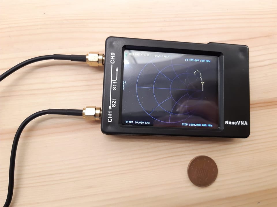
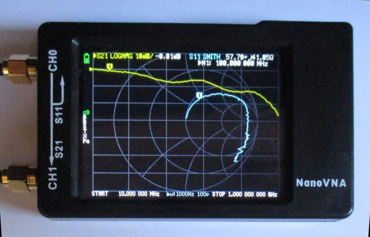
The Smith chart is a graphical way to show impedance across a range of frequencies at once. Dead center of the chart is a perfect 50-ohm match. Points closer to the center are better. Points near the edges are far off. For now, just know that you want the marker at 915 MHz to be somewhere near the middle.
Calibrate before you measure anything
Calibration is the step most beginners skip. Don't skip it. Without it, you're measuring the cable and connectors along with your antenna, and the numbers will lie to you.
The NanoVNA ships with three small standards: an open (nothing connected), a short (a shorted cap), and a 50-ohm load (a tiny terminator). Calibration teaches the instrument what its own hardware looks like so it can subtract that from future measurements.
Here's how to do it:
- Attach your measurement cable to Port 1 (labeled CH0 on most units).
- Open the calibrate menu. Set your frequency range. For 915 MHz Meshtastic work, 700 MHz to 1200 MHz covers the band with room to see context on either side.
- Connect the open standard to the end of the cable. Tap "Open." Wait for it to finish.
- Connect the short. Tap "Short." Wait.
- Connect the 50-ohm load. Tap "Load." Wait.
- Tap "Done" or "Save cal."
After calibration, the display should show the load as nearly flat at the center of the Smith chart and SWR at or very close to 1.0. If it looks messy, something went wrong. Check that the standards are fully tightened and redo it.
Recalibrate any time you swap cables, change adapters, or change your frequency range. Calibration is only valid for the exact cable and port you calibrated on.
Connecting your antenna
Remove the calibration standard and connect your antenna to the end of the measurement cable. Your radio should be off or connected to a dummy load, not the antenna you're testing.
SMA antennas connect directly. If your antenna has an N-type or BNC connector, use an adapter. The adapter adds a tiny bit of error, but it's small enough to ignore for hobby work. Make sure every connection is finger-tight.
Reading the SWR graph
You should see a curve with frequency along the bottom and SWR up the side. Move the marker to 915 MHz. The display will show the SWR value at that frequency.
What you're looking for:
- A dip in the curve somewhere near 915 MHz. That dip is resonance, the frequency where the antenna does its best work.
- The dip going below 2.0, ideally below 1.5.
- A smooth curve. Jagged or noisy traces usually mean a loose connector or a failing cable, not a bad antenna.
If the dip is at the right place and the right depth, your antenna is good. Write the SWR value down and you're done.
When the numbers are off
A dip in the wrong place means the antenna is resonant at the wrong frequency.
Dip is below 915 MHz: the antenna is too long. Trim it. On a quarter-wave ground plane at 915 MHz, each millimeter you remove shifts resonance up by roughly 1 to 2 MHz. Make small cuts, remeasure after each one. You can always cut more; you can't uncut.
Dip is above 915 MHz: the antenna is too short. You can't easily add material to a trimmed element, but check whether your radials are also too short, or whether a poorly installed connector is consuming length it shouldn't.
Dip is present but very shallow (SWR not going below 3.0): usually a connection problem, not the antenna itself. Check the SMA connector solder joints and the cable ends. A cold solder joint looks exactly like a badly tuned antenna on the graph.
No dip at all: likely an open circuit somewhere. Check for a broken element, a disconnected center conductor, or a connector that's making no electrical contact.
Purchased antennas
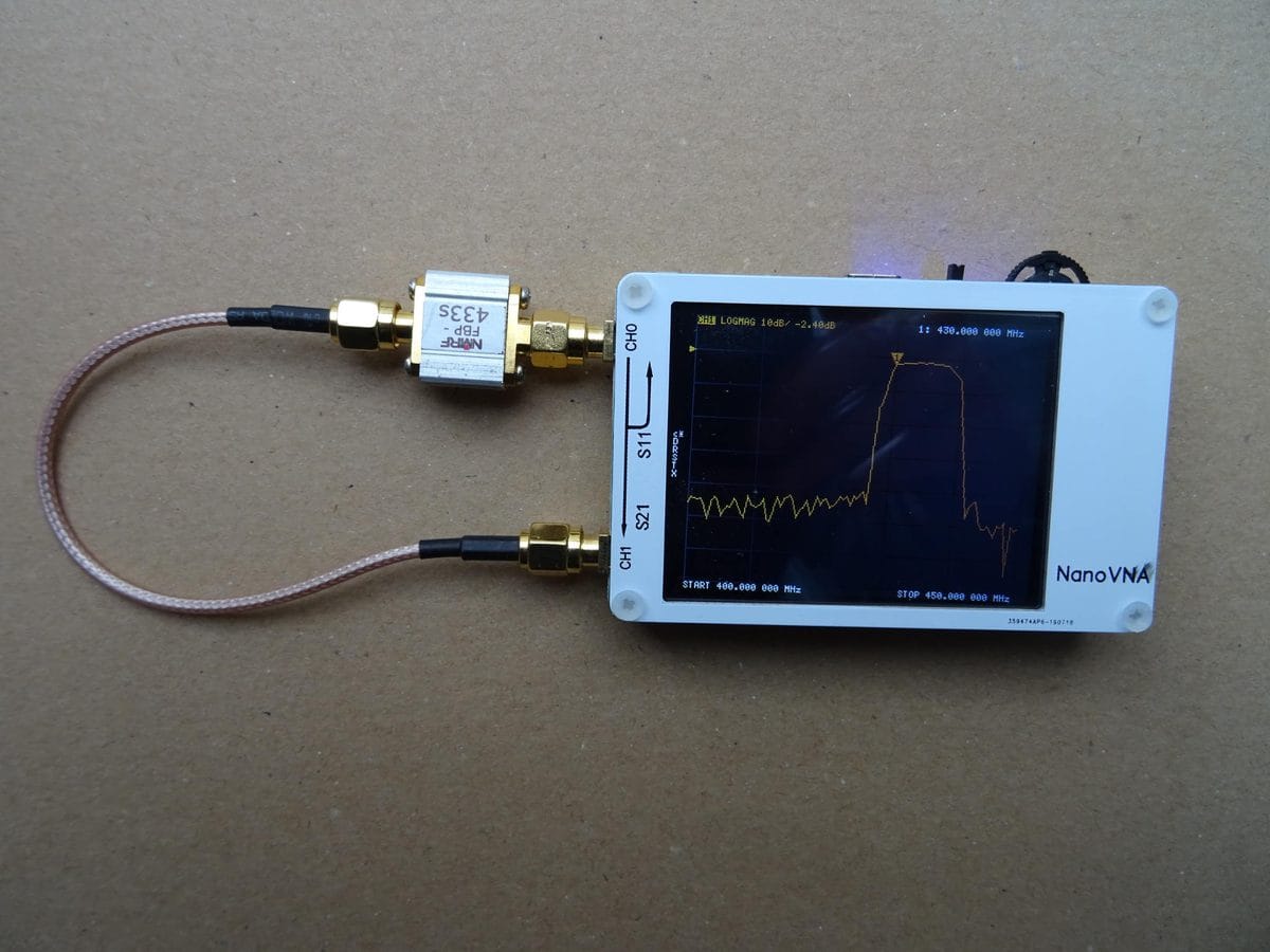
Most stock rubber duck antennas shipped with Meshtastic hardware are tuned for 433 MHz or 868 MHz bands, not 915 MHz. Put yours on the NanoVNA before assuming it's good. Some are fine. Some aren't even close.
Aftermarket 915 MHz antennas from name-brand suppliers like Taoglas or Linx typically measure well out of the box. Generic antennas from AliExpress are a coin flip. The NanoVNA will tell you in about 30 seconds which one you have.
Homebrew antennas
If you built the ground plane or slim-jim from our antenna post, expect your first measurement to be close but not exact. Wire antennas pick up small errors from cut length, solder blobs, and the surface you're mounting them on. That's normal. Measure, trim or adjust, remeasure. Three passes usually gets you there.
One useful trick: measure your antenna before you mount it, then again after you put it in the enclosure or on the mast. Nearby metal changes the resonant frequency. If the SWR was good on the bench but not great once mounted, the mounting environment is absorbing some of the tune. Compensate during the bench phase by trimming slightly shorter than calculated, then confirm once mounted.
That's the whole workflow. Calibrate, connect, read the dip, adjust if needed. A $60 NanoVNA and twenty minutes of bench time will tell you more about your antenna than a year of wondering why the range isn't what you expected.